> For the complete documentation index, see [llms.txt](https://setup.livereach.ai/llms.txt). Markdown versions of documentation pages are available by appending `.md` to page URLs; this page is available as [Markdown](https://setup.livereach.ai/installation-guide/network.md).

# 3. Connect the network

Follow the cables from each appliance to the router, switch, cameras, and optional relay.

## Before you start

Choose the layout with your network administrator and LiveReach deployment contact. Confirm the available Ethernet ports, device addresses, and any required network settings before connecting the equipment.

The NVR has **two Ethernet ports**. SafeTunnel appliances may have **one or two**. The drawings show a separate connection for each port used.

{% hint style="info" %}
**Match each socket to its destination.** Connections below are named for what they connect to: the router, camera switch, or relay. Have LiveReach identify the physical socket configured for each connection, then label the cables. Socket positions in the drawings are illustrative.
{% endhint %}

## Choose your layout

| Layout                        | Connections used                                                                                                                                           |
| ----------------------------- | ---------------------------------------------------------------------------------------------------------------------------------------------------------- |
| **1 · Shared switch**         | One Ethernet port on each appliance. Cameras and the optional relay join the same switch.                                                                  |
| **2 · Direct relay**          | Two ports on the NVR: one toward the router and one toward the camera switch. SafeTunnel uses one toward the router and a second for the relay, if fitted. |
| **3 · Camera / relay switch** | Two ports on each appliance: one toward the router and one toward the switch shared by cameras and the optional relay.                                     |

**Router connection** means a connection to the site router’s local network, either directly or through the site’s existing network switch. Your network administrator identifies the correct connection point.

## Connect the selected layout

Follow the Ethernet lines in the diagram. The **globe is the internet**, the **router connects the site network to it**, and the **switch connects the local devices**. Dashed connections are used only when a relay is installed. The relay’s separate controls wiring is covered in [Connect the optional relay](/installation-guide/relay.md).

{% tabs %}
{% tab title="1 · Shared switch" %}

### Setup 1 — All devices share a switch

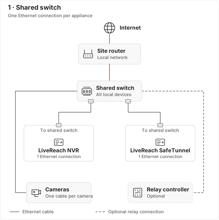
<figure><img src="https://3748104918-files.gitbook.io/~/files/v0/b/gitbook-x-prod.appspot.com/o/spaces%2Fcfh08s1E8Fn9MOdqduSf%2Fuploads%2FwZGdaarMnS7b1jMcQOK7%2Fnetwork-shared.svg?alt=media" alt="Internet globe connected to a site router, then to a shared switch. Separate switch connections go to the NVR, SafeTunnel, cameras, and optional relay. Each appliance uses one Ethernet port."><figcaption><p>Each appliance uses one Ethernet connection to the shared switch. Omit the relay connection if no relay is fitted.</p></figcaption></figure>

| Connect from                   | Connect to    |
| ------------------------------ | ------------- |
| NVR — one Ethernet port        | Shared switch |
| SafeTunnel — one Ethernet port | Shared switch |
| Each camera                    | Shared switch |
| Relay controller, if fitted    | Shared switch |
| Shared switch — uplink         | Site router   |

Use a separate switch port for each connected device. The NVR, SafeTunnel, cameras, and relay communicate through this shared network.
{% endtab %}

{% tab title="2 · Direct relay" %}

### Setup 2 — Separate camera switch and a direct relay connection

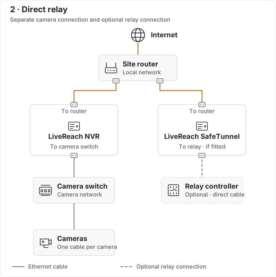
<figure><img src="https://3748104918-files.gitbook.io/~/files/v0/b/gitbook-x-prod.appspot.com/o/spaces%2Fcfh08s1E8Fn9MOdqduSf%2Fuploads%2FAjNN4aD0cAvGuRpONjIW%2Fnetwork-direct-relay.svg?alt=media" alt="Internet globe connected to the site router. One Ethernet port on each appliance connects toward the router. The NVR&#x27;s other port connects to a camera switch, which connects to the cameras. SafeTunnel&#x27;s other port connects directly to the optional relay."><figcaption><p>The NVR uses separate router and camera connections. SafeTunnel needs a second Ethernet port when the relay is fitted.</p></figcaption></figure>

| Connect from                                           | Connect to                  |
| ------------------------------------------------------ | --------------------------- |
| NVR — router connection                                | Site router’s local network |
| NVR — other Ethernet port                              | Camera switch               |
| SafeTunnel — router connection                         | Site router’s local network |
| SafeTunnel — other Ethernet port, if a relay is fitted | Relay controller directly   |
| Each camera                                            | Camera switch               |

The NVR and SafeTunnel communicate through the router’s local network. Cameras reach the NVR through the camera switch. The optional relay has its own direct connection to SafeTunnel.

Have LiveReach and the network administrator configure the addresses at both ends of the direct relay connection. Connecting the cable alone does not configure it.
{% endtab %}

{% tab title="3 · Camera / relay switch" %}

### Setup 3 — Cameras and relay share a separate switch

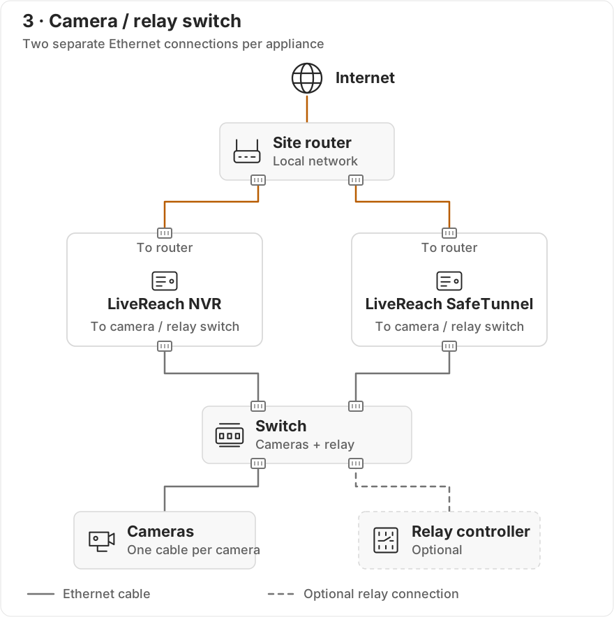
<figure><img src="https://3748104918-files.gitbook.io/~/files/v0/b/gitbook-x-prod.appspot.com/o/spaces%2Fcfh08s1E8Fn9MOdqduSf%2Fuploads%2F9Vjo7sFjJbS6W2MS6vTX%2Fnetwork-camera-relay.svg?alt=media" alt="Internet globe connected to the site router. One Ethernet port on each appliance connects toward the router. The other port on each appliance connects to a shared camera and relay switch. Cameras and the optional relay also connect to that switch."><figcaption><p>Each appliance uses two Ethernet connections: one toward the router and one toward the camera / relay switch.</p></figcaption></figure>

| Connect from                     | Connect to                  |
| -------------------------------- | --------------------------- |
| NVR — router connection          | Site router’s local network |
| NVR — other Ethernet port        | Camera / relay switch       |
| SafeTunnel — router connection   | Site router’s local network |
| SafeTunnel — other Ethernet port | Camera / relay switch       |
| Each camera                      | Camera / relay switch       |
| Relay controller, if fitted      | Camera / relay switch       |

Both appliances join the router’s local network and the separate camera / relay network. Cameras reach the NVR and the relay reaches SafeTunnel through the camera / relay switch. Have LiveReach confirm which appliance addresses the configuration uses.
{% endtab %}
{% endtabs %}

{% hint style="info" %}
**Keep the two connections configured for their intended roles.** In setups 2 and 3, connecting an appliance to both networks does not automatically provide internet access to the cameras. Have your network administrator apply the site’s addressing, routing, and firewall plan.
{% endhint %}

## Verify the required paths

Use these checks after the devices are powered and configured. Link lights or a successful ping are useful diagnostics, but do not prove the application connection works.

| Required path                     | Evidence to record                                                                                                                      |
| --------------------------------- | --------------------------------------------------------------------------------------------------------------------------------------- |
| **Cameras → NVR**                 | Each named camera provides a stable live stream to the NVR.                                                                             |
| **NVR ↔ SafeTunnel**              | LiveReach confirms the appliance connection and each intended camera in SafeTunnel.                                                     |
| **Relay ↔ SafeTunnel**, if fitted | The configured relay is reachable from SafeTunnel using the site’s configuration. Test output behavior separately during commissioning. |

Record the selected layout, each cable’s destination, the physical socket used, and device addresses in the [worksheet](https://3748104918-files.gitbook.io/~/files/v0/b/gitbook-x-prod.appspot.com/o/spaces%2Fcfh08s1E8Fn9MOdqduSf%2Fuploads%2FERwcsHzx0cLE0p89nrVV%2Finstallation-worksheet.pdf?alt=media). Its network page includes all three connection lists for offline use.

## Check before continuing

* [ ] The appliances have enough Ethernet ports for the selected layout.
* [ ] Each cable is connected to the configured socket and labeled with its destination.
* [ ] The network administrator has checked addressing and required communication paths.
* [ ] Camera streams and appliance connectivity have passed, or are explicitly recorded as pending until camera installation and configuration are finished.
* [ ] Any connection issue has an owner before commissioning proceeds.

**Next:** [Install and aim cameras →](/installation-guide/install.md)